The blade deviation measurement system BE 2020 is used to measure the lateral movement of the blade during the running sawing operation. The sawyer can thus drive continuously with optimum feed speed, even with decreasing blade sharpness. The edges are cut straighter and require less or no rework. You can increase the throughput and thus the profitability of your company permanently.
- Compliance to tight cutting tolerances
- Increase of the feed speed up to a specified blade deviation
- Prevention of blade overuse; hence longer service life with lower maintenance costs
- Installation of an automatic feed control possible
- Warning in case of technical malfunction, e.g. wear on guides, blunt saw blade, blade damages, bearing damage on rollers, etc.
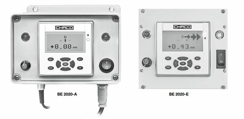
The unit is available in two build versions: as a mounting model in a robust industrial housing for external installation, or as a built-in model for integrated installation into an existing control panel or electronics rack (standard height 3U).
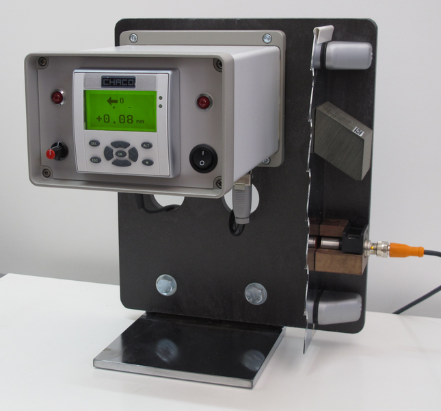
A sensor is installed at a small distance to the side wall of the saw blade. The sensor works according to the eddy-current principle and thus completely contactless. Its signal passes through a cable to the processing electronics. The signal cable is included in the delivery and supplied ready for installation (standard lengths from stock, special lengths available).
The digital layout of the processing electronic ensures high precision and best long-term stability. The blade deviation is shown numerically in the lower area of the display. In the upper half of the screen, the deviation is graphically displayed by a rising arrow in direction and size. If an adjustable threshold is exceeded, a red warning light will also light up on the display.
The electronics provide an analogue signal which can be looped into an automatic feed regulation. Also, a potential-free contact is available with which an external warning device can be controlled.
Technical data and dimensions
Measuring range [mm] ± 1 (at 2.5mm blade distance in idle mode)
Measuring resolution [mm] 0.01
Alarm range [mm] ± 1 (adjustable in increments of 0.01)
Voltage [V] 90 - 264 AC - 50/60 Hz - single-phase
Power consumption [VA] max. 50
Outputs - Absolute output signal, analogue 0 - 10 V
- Potential-free contact, up to 60 V, 1 A
Working temperature - 10 to + 40 °C / 14 to 104 °F
Sensor Inductive sensor Ø 18 mm, stainless body,
supplied by the electronic unit
Cable 4x 0.5mm2, shielded, maximum cable
length 50m
Model for external W 172 x H 134 x D 210 mm
installation BE2020A
Model for integrated W 142 x H 130 x D 180 mm
installation BE2020E